“windsock” (19%) - allows easiest measurement and implantation of LAAO devices
“cauliflower” (3%)
Pre-implant scan
CT provides accurate measurements of the LAA ostial diameter, landing zone diameter, and LAA length, which are vital for accurate sizing of the device. CT allows evaluation of the relationship with the pulmonary veins and other adjacent structures that can be injured during the procedure. CT also simulates procedural fluoroscopic angles and provides evaluation of the interatrial septum, which is punctured during LAA closure. (Source)
Use Shift-Ctrl and draw on the portions of the heart corresponding to the LAA and relevant surrounding tissue → the LAA will “grow” 🪴 from this seed 🌱.
📝 do this at end-systole (when LA and LAA are largest)
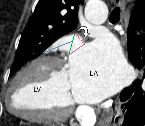
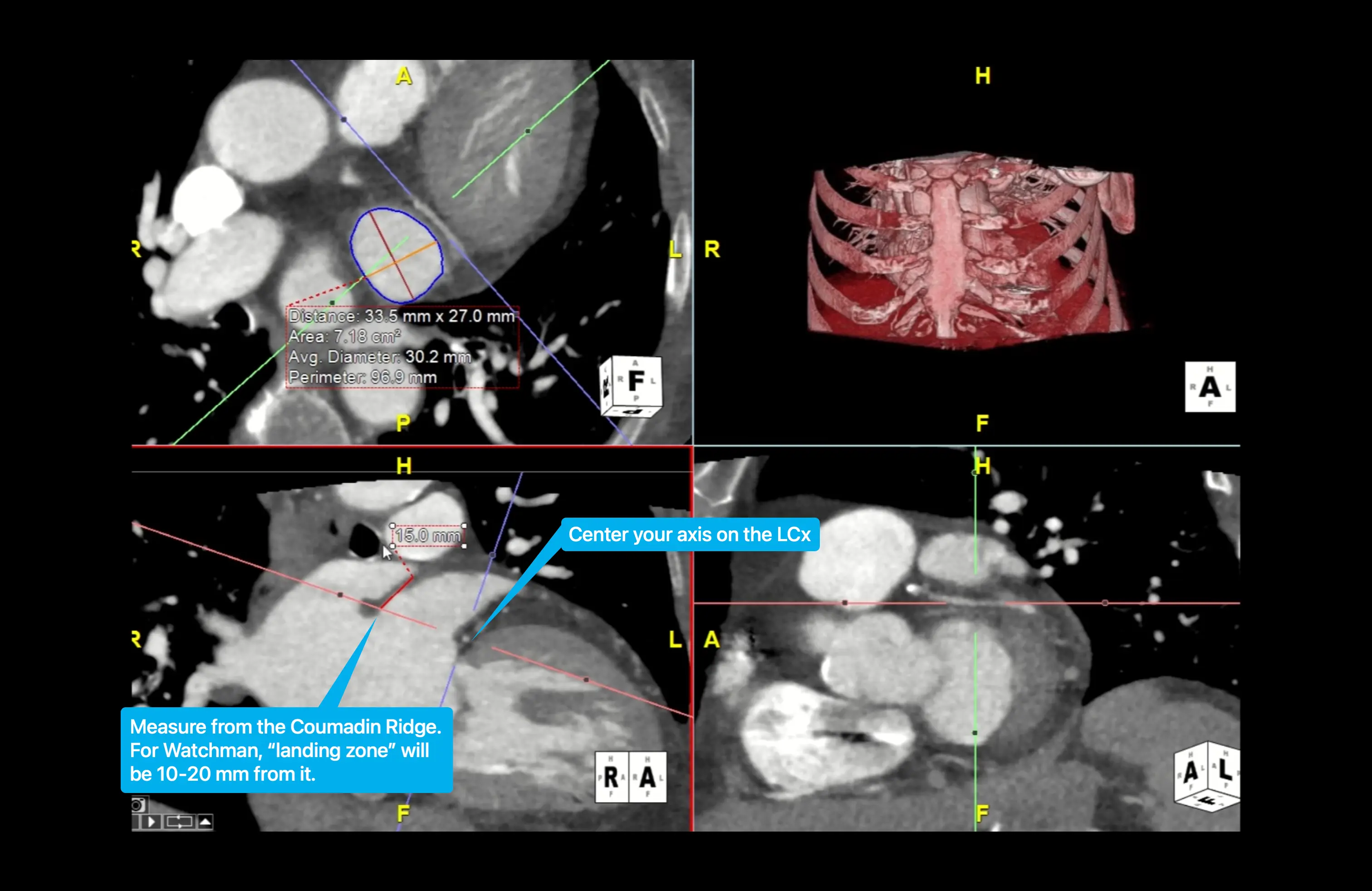
At CT, the landing zone is identified on the long-axis LAA view. For the Watchman device, the landing zone is located 10–20 mm inside the LAA from the Coumadin ridge (aka limbus). The landing zone diameters for the Watchman device are measured on an en-face-view CT image obtained at a line that connects the LAA adjacent to the left circumflex artery to the point 10–20 mm inward of the Coumadin ridge. 1
Caption: Vertical long-axis-view CT image of the left ventricle (LV) shows how the landing zone for a Watchman device is identified at a distance of 10–20 mm (red dotted line) distal to the Coumadin ridge (arrow). The pink line is the LAA ostium. The landing zone diameter is measured in the plane between this point and the point where the left circumflex artery is located (green line). The length of the LAA is also measured on the same image from the landing zone to the tip of the dominant lobe (blue line).
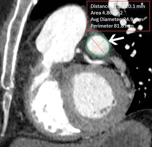
Caption: En-face-view CT image shows the cross-sectional view of the landing zone (arrow), where the maximum diameter, minimum diameter, and perimeter are measured.
Post-implant
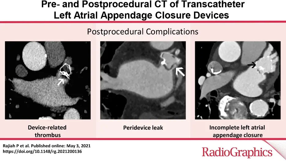
CT can be used to pick-up complications including:
incomplete closure
peri-device leak
device-related thrombus
device dislodgement
Footnotes
Rajiah P, Alkhouli M, Thaden J, Foley T, Williamson E, Ranganath P. Pre- and Postprocedural CT of Transcatheter Left Atrial Appendage Closure Devices. Radiographics. 2021 May-Jun;41(3):680-698. doi: 10.1148/rg.2021200136. PMID: 33939541. ↩↩2↩3