- Related:
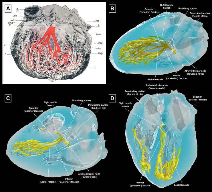
- Tawara illustration of the AV conducting system 1
- Impedance is the term applied to the resistance to current flow in the pacing system
- Recall, Ohm’s Law:
- where is the voltage, is the current, and is the resistance
- Ohm’s Law is typically used for calculating impedance. In reality, impedance and resistance are not synonymous terms. Impedance implies inclusion of all factors contributing to current flow impediment, including lead conductor resistance, electrode resistance, resistance d/t electrode polarization, capacitance and inductance.
- Recall, Ohm’s Law:
- The single most important lead design ∆ to alter pacing threshold evolution was the incorporation of steroid elution at the lead tip to blunt the local inflammatory response.
- Before this, myocardial stimulation thresholds could fluctuate quite a bit in the first weeks after implantation
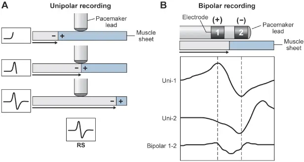
Intracardiac Electrograms
- Ventricular electrograms typically are much larger than atrial electrograms b/c ventricular mass is greater
- Ventricular electrograms: 5-25 mV; Max frequency (in sinus) 10-30 Hz
- Atrial electrograms: 1.5-5 mV; Max frequency (in sinus) 80-100 Hz
- Pulse generator filtering systems attenuate signals outside of these ranges (avoid unwanted sensing)
- 📝 Shortening of tip-to-ring spacing has also improved atrial sensing and rejection of far-field R waves
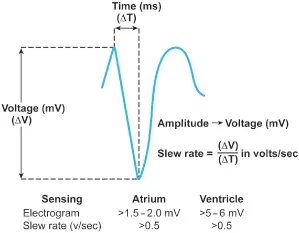
- Slew rate
- the peak slope of the developing electrogram
- represents the maximal rate of change of the electrical potential between the sensing electrodes
- is the first derivative of the electrogram ()
- An acceptable slew rate should be at least 0.5 V/s in both the atrium and the ventricle.
- In general, the higher the slew rate, the higher the frequency content and the more likely the signal will be sensed. Slow, broad signals, such as those generated by the T wave, are less likely to be sensed because of a low slew rate and lower frequency density.
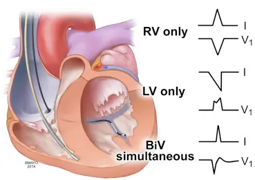
ECG Appearance
- The QRS morphology is specific for a given pacing site
- RV apical pacing
- Lead I: tall R wave
- V1: LBBB-like pattern
- LV pacing
- Lead I: QS complex
- V1: RBBB-like pattern
- Negative or isoelectric complexes in II, III, aVF
- BiV pacing
- Fused vector that resembles a hybrid b/w lone-RV and lone-LV pacing
- Tips
- If the BiV-paced QRS morphology matches the lone-RV pacing morphology despite a good LV threshold, then either prolonged capture latency or significant conduction delay from the LV pacing site is present. By progressively pacing the LV lead earlier than the RV lead while monitoring the QRS for fusion (hybrid QRS complexes) during BiV stimulation, the V-V can be optimized.
- In certain situations (septal infarcts) an offset may need to be programmed, whereby the RV lead is paced earlier than the LV lead.
- RV apical pacing
Footnotes
-
Vijayaraman P, Chelu MG, Curila K, Dandamudi G, Herweg B, Mori S, Jastrzebski M, Sharma PS, Shivkumar K, Tung R, Upadhyay G, Vernooy K, Welter-Frost A, Whinnett Z, Zanon F, Ellenbogen KA. Cardiac Conduction System Pacing: A Comprehensive Update. JACC Clin Electrophysiol. 2023 Nov;9(11):2358-2387. doi: 10.1016/j.jacep.2023.06.005. Epub 2023 Aug 16. PMID: 37589646. ↩